Ready
Porting ESP-Hosted from Raspberry Pi to BeagleV-Fire: A Bring-Up Journey
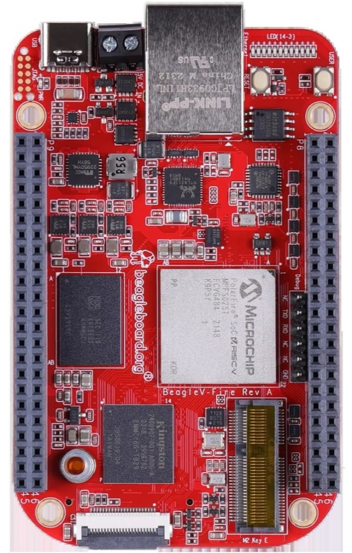
The BeagleV-Fire is a RISC-V SBC built around Microchip’s PolarFire SoC. The ESP-Hosted project lets a Linux host treat an ESP32 as its WiFi/Bluetooth radio over SPI, SDIO, or UART. Both are great pieces of hardware. The catch: ESP-Hosted was written, tested, and documented against the Raspberry Pi. Getting it working on a RISC-V board with a PolarFire SoC and an FPGA-routed SPI bus turned out to be a multi-day exercise in peeling back every layer of the Linux device stack — from shell scripts and device-tree compilation, through GPIO controller capabilities, to SPI signal integrity at the physical wire.
This is a write-up of that port. If you’re trying to bring ESP-Hosted up on anything that isn’t a Pi, most of these issues will probably bite you in some form.
The setup
- Host: BeagleV-Fire running Debian Trixie (kernel
6.12.48-linux4microchip+fpga-2025.10-...) - Radio: ESP32-C6 flashed with ESP-Hosted NG firmware (
NG-1.0.5.0.5) - Transport: SPI (with handshake and data-ready GPIO signals)
- Gateware: CAPE-COMMS (a custom FPGA bitstream that routes SPI/I2C/UART out to the P8/P9 headers)
- Goal: A working
wlan0interface that can scan, associate, and route traffic over WiFi
The ESP-Hosted driver source tree comes with a Raspberry-Pi-flavored rpi_init.sh, GPIO numbers like 22 and 27 baked into headers, and a build process that assumes you’re cross-compiling against the Pi’s kernel. None of that applies on a BeagleV-Fire — but the driver itself is mostly portable C. The work is figuring out which knobs to turn so it talks to the right hardware on the right pins.
Porting the bring-up scripts
The Pi version of the bring-up flow centres on a script called rpi_init.sh. It does what you’d expect — sets a few module parameters, modprobes the kernel module, and prints a few status lines. On a BeagleV-Fire, what needs to happen is similar in shape, but different in almost every detail. The Pi script assumes:
- The kernel module is installed in the system’s
/lib/modules/...tree. - GPIO numbering follows the Raspberry Pi’s
BCMconvention. - The SPI controller is the Pi’s
spi0and is reliably exposed on the well-known header pins. - No other driver will be holding chip-select 0.
None of those hold on the BeagleV-Fire. The module is built out-of-tree and lives in your home directory until you copy it somewhere. GPIO numbers start at 512 (more on that below) and bear no relation to Pi pin numbers. The SPI controller you want is whatever your FPGA gateware actually routes out to the header — in our case, spi@20108000 (CAPE-COMMS routes this one). And spi0.0 is very likely already claimed by something the device tree instantiated at boot.
Here’s the BeagleV-Fire equivalent of rpi_init.sh that emerged from this work:
#!/bin/bash
set -e

MODULE=esp32_spi.ko

# 1. Defensively unbind any driver squatting on spi0.0.
#    On a Pi this isn't needed; on the BeagleV-Fire, the DTS
#    almost always has SOMETHING claiming chip-select 0.
if [ -L /sys/bus/spi/devices/spi0.0/driver ]; then
    CURRENT_DRV=$(basename $(readlink /sys/bus/spi/devices/spi0.0/driver))
    echo "spi0.0 currently bound to: $CURRENT_DRV — unbinding"
    echo "spi0.0" | sudo tee /sys/bus/spi/drivers/$CURRENT_DRV/unbind > /dev/null
fi

# 2. Unload any previous instance of the module.
sudo rmmod esp32_spi 2>/dev/null || true

# 3. Load the module.
sudo insmod "$MODULE"

# 4. Wait for wlan0 to appear. On the Pi this is instant;
#    on the BeagleV-Fire there's a delay while the ESP boots and
#    the ESP-Hosted handshake completes.
echo "Waiting for wlan0 to appear..."
for i in {1..10}; do
    if ip link show wlan0 &>/dev/null; then
        echo "wlan0 is up"
        ip link show wlan0
        exit 0
    fi
    sleep 1
done

echo "wlan0 did not appear within 10 seconds. Check dmesg."
dmesg | tail -30
exit 1
The unbind step at the top is the single most important difference from the Pi script. On the Pi, spi0.0 is empty unless you’ve explicitly enabled a SPI device tree overlay; on the BeagleV-Fire, the base DTS almost certainly has something on CS 0 already. Trying to load the module without first unbinding that something is the first error you’ll hit.
Beyond the script, the driver source itself needed source-level changes that the Pi script can’t help with — GPIO numbers, bus number, and a clock cap (all covered below). If I were upstreaming this, I’d convert those into module_params so a single binary could be configured per-board without rebuilding. As things stand, you make, scp, insmod, and the script handles the choreography around that. In short, cross-compile the driver and send to BeagleV.
With the script in place, attempting to actually load the module on the BeagleV-Fire is where the real porting work begins.
Layer 1: The spidev chip-select conflict
First attempt to load the module:
[ 4938.268809] spi spi0.0: chipselect 0 already in use
[ 4938.273913] esp32_spi: spi_dev_init: Failed to add new SPI device
spi0.0 was claimed by something else. A quick look at /sys/bus/spi/drivers/ showed spi-nand, spi-nor, mmc_spi, and microchip_mpf_spi_fpga_mgr — but spidev wasn’t actually in the kernel. That meant the device tree was creating an SPI device on spi0, CS 0, that was claiming the chip-select before ESP-Hosted could.
Looking at the DTS:
spi@20108000 {
    compatible = "microchip,mpfs-spi";
    /* ... */
    esp32_spi@0 {
        compatible = "rohm,dh2228fv";
        reg = <0>;
        spi-max-frequency = <40000000>;
    };
};
The "rohm,dh2228fv" is a well-known trick — it’s used as a placeholder compatible string to instantiate a generic SPI device without triggering the "spidev: buggy DT" warning. But for our purposes it’s not a placeholder, it’s a conflict: it grabs the chip-select before ESP-Hosted’s spi_new_device() runs.
Fix: Remove the esp32_spi@0 child node entirely. The ESP-Hosted driver registers its own device programmatically — it never reads this DTS node. The placeholder serves no purpose here and actively gets in the way.
Recompile the DTS:
dtc -I dts -O dtb -o beaglev_fire.dtb beaglev_fire.dtsReboot, reload the module — chip-select conflict gone.
(One word of caution: don’t edit the DTS in /boot in place. Compile to a new filename, test that it boots, and only then swap the DTB over the original. I learned this the hard way after one ill-fated edit dropped me at the RISC-V # U-Boot prompt with no kernel. Recovering took an hour.)
Layer 2: GPIO numbers don’t translate from the Pi
Next error:
esp32_spi: spi_dev_init: Failed to obtain GPIO for Handshake pin, err:-517Error -517 is -EPROBE_DEFER, which usually means “the GPIO controller isn’t ready yet” — but in this case it just meant the GPIO number didn’t exist on this board. The driver was asking for GPIO 22 (the Pi’s BCM 22), and on the BeagleV-Fire there is no GPIO 22.
Why? Because Linux GPIO numbering is per-system, allocated by GPIO controllers at boot. On the Pi, the SoC GPIO controller starts at 0. On the BeagleV-Fire, looking at /sys/kernel/debug/gpio:
gpiochip0: GPIOs 512-525, parent: platform/20120000.gpio
gpiochip1: GPIOs 526-549, parent: platform/20121000.gpio
gpiochip2: GPIOs 550-581, parent: platform/20122000.gpio
gpiochip3: GPIOs 582-597, parent: platform/41100000.gpio
gpiochip4: GPIOs 598-618, parent: platform/41200000.gpio
gpiochip5: GPIOs 619-638, parent: platform/44000000.gpio
Everything starts at 512. There is no GPIO 22. The driver’s hard-coded “Raspberry Pi BCM pin” numbers needed to be mapped to actual BeagleV-Fire GPIO line numbers corresponding to whichever P8/P9 header pins you’ve physically wired to.
This is one of the porting steps that’s easy to miss if you’re following a Pi tutorial. The driver header has #define HANDSHAKE_PIN 22 (or similar); on the BeagleV-Fire it needs to be #define HANDSHAKE_PIN 562 (P8_15) or whichever pin you’ve wired.
Layer 3: Not every GPIO controller supports interrupts
Updated the GPIO numbers to ones that physically existed (608 = P9_23 on gpiochip4). New error:
esp32_spi: spi_dev_init: Failed to request IRQ for Handshake pin, err:-22-22 is -EINVAL. The pin existed and could be requested as a GPIO — but couldn’t be used as an interrupt source.
Looking at /proc/interrupts:
102: 0 0 0 0 MPFS GPIO 31 Edge spi1.1 cdOnly gpiochip2 (the MPFS GPIO at 20122000.gpio) had any registered IRQs. The FPGA-fabric GPIO controllers (gpiochip3, gpiochip4 at 41100000.gpio and 41200000.gpio) didn’t appear at all — they don’t expose an interrupt parent, so any IRQ request on them fails with -EINVAL.
Lesson: For any GPIO you need to use as an IRQ source on the BeagleV-Fire, pick a pin on gpiochip2 (MPFS GPIO, GPIOs 550–581). The FPGA-fabric GPIOs (COREGPIO) can do level I/O but not interrupts in this gateware configuration.
Moved the handshake pin to GPIO 562 (P8_15), data-ready to GPIO 563 (P8_16). Module loaded:
SPI Handshake GPIO configured at pin 562 with IRQ 118
SPI Data Ready GPIO configured at pin 563 with IRQ 119
SPI device initialized successfully
But: no wlan0 interface.
Layer 4: The IRQs fire, but does data actually move?
/proc/interrupts showed both 118 and 119 incrementing, which meant the ESP was raising its handshake lines and the BeagleV was receiving them. Good — that’s the IRQ side proven. But no network interface was registering, which meant the ESP-Hosted protocol handshake itself wasn’t completing.
To see what was actually crossing the wire, I added two debug prints inside the driver’s esp_spi_work() function. One log line to show GPIO levels and data_path state at every workqueue invocation, and a print_hex_dump() of the RX buffer right after spi_sync_transfer():
esp_err("WORK: trans_ready(HS)=%d rx_pending(DR)=%d data_path=%d\n",
        trans_ready, rx_pending, data_path);

ret = spi_sync_transfer(spi_context.esp_spi_dev, &trans, 1);

print_hex_dump(KERN_ERR, "rx: ", DUMP_PREFIX_OFFSET,
               16, 1, trans.rx_buf, 32, true);
Using esp_err and KERN_ERR for the dump means the messages always show up in dmesg regardless of the driver’s verbosity setting. Useful when you don’t know what log level the verbose-dump macros are gated behind.
The result was diagnostic:
WORK: trans_ready(HS)=1 rx_pending(DR)=1 data_path=1
rx: 00000000: ff ff ff ff ff ff ff ff ff ff ff ff ff ff ff ff  ................
rx: 00000010: ff ff ff ff ff ff ff ff ff ff ff ff ff ff ff ff  ................
All 0xFF. The handshake gate was opening correctly — the ESP was signaling ready, the driver was clocking out a real transaction — but MISO was reading as floating high the whole time. The host was sending bits, but the ESP either wasn’t being selected (CS not toggling) or its MISO line wasn’t reaching the BeagleV.
The all-0xFF pattern is diagnostic. The other possibilities each have their own signature:
- All
0x00→ MISO grounded or dead bus - All
0xFF→ MISO floating, pulled up (which is what we had) - Changing random garbage → signal integrity / clock issue
- Structured but mangled bytes → mode mismatch or bit-shift
After re-checking and reseating the physical wiring (the ESP-C6’s MISO is GPIO2, the BeagleV’s spi0 MISO is on a CAPE-COMMS-routed header pin), the next dump showed real bytes:
rx: 00000000: 01 80 00 00 0f 80 06 00 72 80 80 00 00 80 0c 00
rx: 00000010: 0b 80 00 00 01 80 86 81 00 8d 00 00 d5 00 86 27
Real data — but not valid data. The driver rejected it:
process_rx_buf: offset_rcv[6] != exp[12], dropThe packet had structure (length-like fields, a header-like pattern) but the bytes were corrupted. That’s the “structured but mangled” signature — and it pointed at signal integrity or clock-edge timing, not mode mismatch.
Layer 5: 10 MHz is too fast for jumper wires
The driver was running at 10 MHz, the default for ESP-Hosted’s initial clock. At 10 MHz over loose jumper wires, with no clean ground return next to the CLK line, the receiver mis-samples bits — exactly what we were seeing.
I dropped SPI_INITIAL_CLK_MHZ from 10 to 5, rebuilt, reloaded, and reset the ESP. The next bootup packet came through clean:
rx: 00000000: 03 00 00 00 1f 00 0c 00 e5 01 00 00 01 00 18 00
rx: 00000010: 17 00 00 00 03 01 0d 02 01 1a 00 01 aa 01 0c 4e
process_esp_bootup_event: Received ESP boot-up event
process_event_esp_bootup: Boot-up Event tag: 3
esp_validate_chipset: Chipset=ESP32-C6 ID=0d detected over SPI
process_event_esp_bootup: Boot-up Event tag: 2
adjust_spi_clock: ESP Reconfigure SPI CLK to 26 MHz
That last line was the next problem. The ESP firmware was telling the host “let’s bump the clock to 26 MHz now.” The host obediently complied, and immediately the next command — Command[0x1], the interface-init command — timed out:
wait_and_decode_cmd_resp: Command[0x1] timed out
cmd_init_interface: ... failure, ret: -22
esp_add_card: esp_add_network_ifaces(adapter) failure, ret: -1
process_event_esp_bootup: network interface init failed
The bootup event went through at the slow clock. The init command had to ride at 26 MHz, and the wiring couldn’t sustain it. The RX dumps confirmed: corruption returned the moment the clock bumped.
Layer 6: Cap the clock
The fix is to refuse the ESP’s renegotiation request. The adjust_spi_clock() function in esp_spi.c is where the clock change is applied; clamping the requested speed there is a one-function change:
static void adjust_spi_clock(u8 spi_clk_mhz)
{
    /* The ESP firmware asks for 26 MHz, but our wiring can't sustain it.
     * Cap to the speed we know is reliable. */
    if (spi_clk_mhz > SPI_INITIAL_CLK_MHZ) {
        esp_info("Capping requested SPI CLK %u MHz to %u MHz\n",
                 spi_clk_mhz, SPI_INITIAL_CLK_MHZ);
        spi_clk_mhz = SPI_INITIAL_CLK_MHZ;
    }

    if ((spi_clk_mhz) && (spi_clk_mhz != spi_context.spi_clk_mhz)) {
        esp_info("ESP Reconfigure SPI CLK to %u MHz\n", spi_clk_mhz);
        spi_context.spi_clk_mhz = spi_clk_mhz;
        spi_context.esp_spi_dev->max_speed_hz = spi_clk_mhz * NUMBER_1M;
    }
}
Rebuild, reload, reset the ESP. The new log:
adjust_spi_clock: Capping requested SPI CLK 26 MHz to 5 MHz
process_event_esp_bootup: Boot-up Event tag: 0
process_event_esp_bootup: Boot-up Event tag: 1
process_fw_data: ESP chipset's last reset cause:
print_reset_reason: POWERON_RESET
check_esp_version: ESP-Hosted Version: NG-1.0.5.0.5
esp_reg_notifier: Driver init is ongoing
And then — finally — wlan0:
systemd-networkd[361]: wlan0: Link UP
systemd-networkd[361]: wlan0: Gained carrier
$ ip link show wlan0
6: wlan0: <BROADCAST,MULTICAST,UP,LOWER_UP> mtu 1500 ...
link/ether 40:4c:ca:5d:e1:98 ...The MAC matches the ESP32-C6’s WiFi MAC reported in its boot log. The interface is real.
Bringing the link up the rest of the way
Once wlan0 existed, the user-space side was conventional. The board uses iwd, so:
$ iwctl
[iwd]# station wlan0 scan
[iwd]# station wlan0 get-networks
                       Available networks
--------------------------------------------------------------------------------
      Network name              Security    Signal
--------------------------------------------------------------------------------
  >   Kisaka the Jones          psk         ****
      Kimoino                   psk         ****
      Lily                      psk         ****

[iwd]# station wlan0 connect "Kisaka the Jones"
After association, systemd-networkd ran DHCP automatically (its wlan0.network file was already in place), and:
$ ip -4 addr show wlan0
6: wlan0: ... state UP ...
    inet 192.168.8.105/24 metric 1024 brd 192.168.8.255 scope global dynamic wlan0
A real IPv4 address.
Final test, with eth0 disabled to force traffic through WiFi:
$ sudo ip link set eth0 down
$ ping google.com
PING google.com (172.217.170.174) 56(84) bytes of data.
64 bytes from mba01s09-in-f14.1e100.net (172.217.170.174): icmp_seq=1 ttl=117 time=146 ms
64 bytes from mba01s09-in-f14.1e100.net (172.217.170.174): icmp_seq=2 ttl=117 time=177 ms
64 bytes from mba01s09-in-f14.1e100.net (172.217.170.174): icmp_seq=3 ttl=117 time=149 ms
...
Replies. DNS works, ICMP works, routing works — every packet going out is going out over SPI to an ESP32-C6 and out over WiFi from there.
A few things I’d do differently
Most of what made this take longer than it had to was being slow to add the right debug instrumentation. Two prints inside esp_spi_work() — the GPIO-level line and the RX hex dump — were what actually moved the needle. Everything before that was speculation. If you’re porting any layered driver to a new board, instrument first and theorise later.
The other big lesson is to suspect the platform when you see crashes that don’t match the code change you just made. I saw RCU stalls and an mmc0 hardware timeout multiple times during this work, and the natural instinct was to keep iterating on the driver. The right move was to verify the board itself was stable at idle before continuing — the platform was probably already marginal from the repeated forced power cycles, and that was injecting noise into my driver experiments. (The lockups appear to be related to sustained heavy-polling load on what’s probably a marginal timer/IPI configuration — something for a future post.)
The hardest single moment was when I edited beaglev_fire.dts in-place, forgot to compile it back to a .dtb, and rebooted into a RISC-V # U-Boot prompt with no kernel. I recovered by booting from a backup .dtb and recompiling, but it cost an hour. Lesson: always copy the original .dtb aside, compile the edited DTS to a new filename, and only swap it in after you’ve confirmed the new one boots. Keep your golden image untouched.
Summary of changes for a BeagleV-Fire ESP-Hosted port
For anyone trying to follow this trail, the concrete changes are:
- Replace
rpi_init.shwith a BeagleV-Fire bring-up script that unbinds any existing driver fromspi0.0beforeinsmod, and waits forwlan0to appear with a timeout. - Remove the
esp32_spi@0child node from the SPI controller in your DTS, or change itscompatibleto something the SPI core won’t bind. Either way, don’t let it claim CS 0. - Update the handshake and data-ready GPIO numbers in
esp_spi.h(or wherever they’re defined) to BeagleV-Fire line numbers. These need to be ongpiochip2(550–581) if you want IRQ support. - Verify SPI bus number. ESP-Hosted defaults to bus 0; CAPE-COMMS exposes
spi0(20108000.spi) on the header. If your gateware routes a different controller, changebus_numaccordingly. - Cap the SPI clock in
adjust_spi_clock(). The ESP firmware will ask to renegotiate up to 26 MHz; refuse anything above what your wiring can sustain (5 MHz on flying jumper leads; a proper PCB cape with ground planes would handle the full speed). - Recompile the DTS to a
.dtband install it correctly — don’t edit a.dtsin/bootand forget the compile step.
After that, the user-space side (iwctl, systemd-networkd, DHCP) is identical to any other Linux WiFi setup.
What the final stack looks like
┌─────────────────────────────────────────────┐
│  User space: iwctl / systemd-networkd / ip  │
└─────────────────────────────────────────────┘
                       │
┌─────────────────────────────────────────────┐
│  Linux: cfg80211 wireless subsystem         │
│  ESP-Hosted driver (esp32_spi.ko)           │
│   ↳ esp_spi_work() ←─── workqueue           │
│   ↳ spi_sync_transfer() → SPI core          │
└─────────────────────────────────────────────┘
                       │
┌─────────────────────────────────────────────┐
│  BeagleV-Fire SoC                           │
│   spi0 (MPFS SPI, 20108000)                 │
│   gpiochip2 (MPFS GPIO, IRQ-capable)        │
│   ↳ HS  → GPIO 562 (P8_15)                  │
│   ↳ DR  → GPIO 563 (P8_16)                  │
└─────────────────────────────────────────────┘
                       │
┌─────────────────────────────────────────────┐
│  CAPE-COMMS FPGA gateware                   │
│   routes MOSI/MISO/CLK/CS to header pins    │
└─────────────────────────────────────────────┘
                       │
              MOSI/MISO/CLK/CS/HS/DR
                       │
┌─────────────────────────────────────────────┐
│  ESP32-C6                                   │
│   ESP-Hosted NG firmware                    │
│   Wi-Fi 6 + BLE radio                       │
└─────────────────────────────────────────────┘
Every layer of that stack got debugged on the way to making it work. The fact that it ends with ping google.com returning steady replies is, frankly, more satisfying than it has any right to be.